
Overview

|

|
Design

The design has 4 main subsections: drivetrain, gripper to capture the miner, bumper to detect collision, and electrical and sensor housing.
When the grippers are in closed state, the robot dimensions are 28 cm × 29 cm × 27 cm.
When the grippers are in closed state, the robot dimensions are 28 cm × 29 cm × 27 cm.
Drivetrain


The drivetrain has two DC motors for power and 2 caster wheels for support. The DC motors are controlled by TLE-5206 motor drivers. For feedback control, Hall effect encoders are placed behind the motor assembly to capture the motor RPM.
Gripper


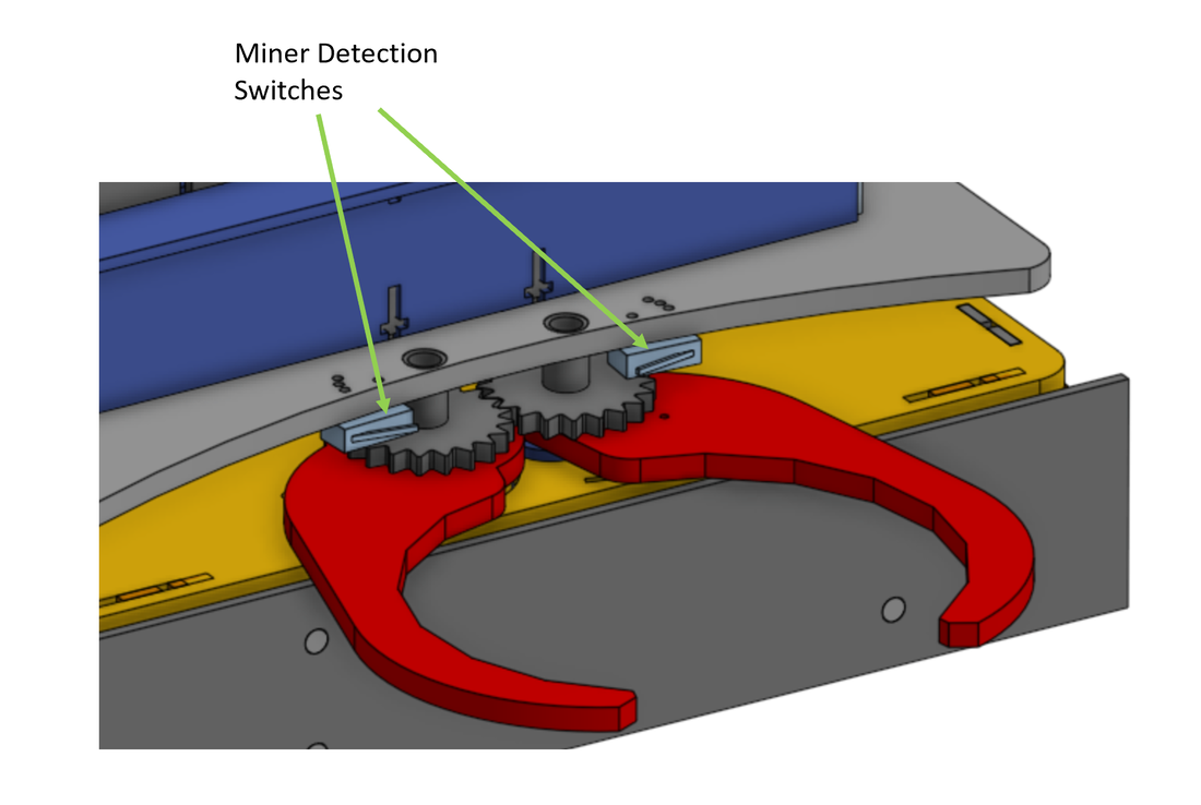
The gripper design consists of two coupled gears. One gear is attached directly to a servo motor while the other is meshed with the first gear. This leads both the gears to rotate in opposite direction when the servo rotates, which guides the gripper arms to close or open simultaneously. This mechanism gets triggered when the flange of the miner hits the switches as shown in the figure above.
Sensor Placement
|
|
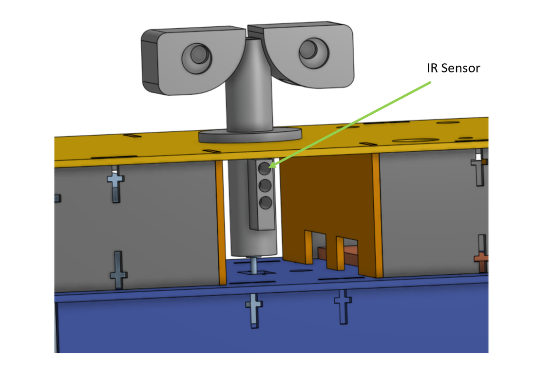
IR Sensor - The holes are positioned such that the middle hole is at the same level as the the IR emitter, while the top and bottom holes are 0.75 cm above and below the IR emitter level respectively. In the final assembly, the IR sensor is placed inside a long tube and placed co-axially with the topmost hole.
Miner Detection Switches - The switches are mounted on the curved plate and positioned such that the flange of the miner would press the switch when it is within the grasping reach of the gripper arms.
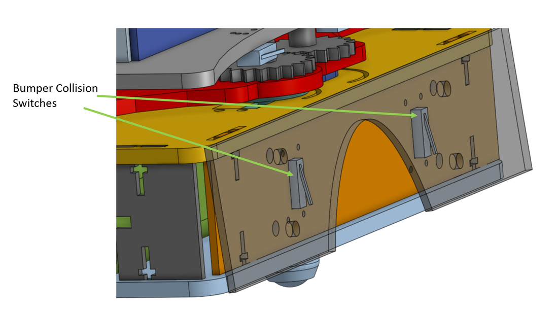
Bumper Collision Switches - Collision detection switches are placed behind the bumper and gets pressed when the bumper hits an object. The design prevents the miner from pressing the switch when it is being captured by the robot but when the robot is moving with the miner, any bumps either to the bumper directly or to the miner presses the switches.
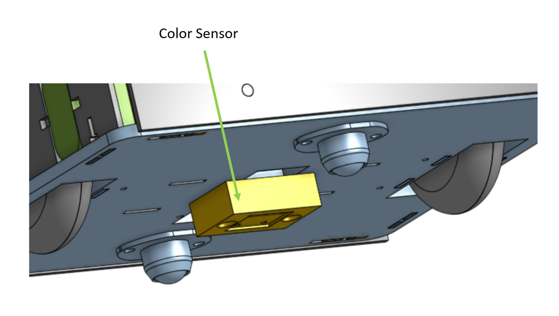
Color Sensor - Color sensor is placed at the center of the underside of the chassis and positioned to be 4 mm above the floor. The height of the sensor is determined empirically while centering is done to allow isolation from ambient lighting conditions.
Accelerometer - During testing it was noticed that accelerometer performance is very sensitive to the length of wire. Therefore, it is placed close to the TIVA on the topmost tier.
Encoders - Encoders are placed behind the motor assembly on the chassis.
Miner Detection Switches - The switches are mounted on the curved plate and positioned such that the flange of the miner would press the switch when it is within the grasping reach of the gripper arms.
Bumper Collision Switches - Collision detection switches are placed behind the bumper and gets pressed when the bumper hits an object. The design prevents the miner from pressing the switch when it is being captured by the robot but when the robot is moving with the miner, any bumps either to the bumper directly or to the miner presses the switches.
Color Sensor - Color sensor is placed at the center of the underside of the chassis and positioned to be 4 mm above the floor. The height of the sensor is determined empirically while centering is done to allow isolation from ambient lighting conditions.
Accelerometer - During testing it was noticed that accelerometer performance is very sensitive to the length of wire. Therefore, it is placed close to the TIVA on the topmost tier.
Encoders - Encoders are placed behind the motor assembly on the chassis.
Bumper Collision Detection
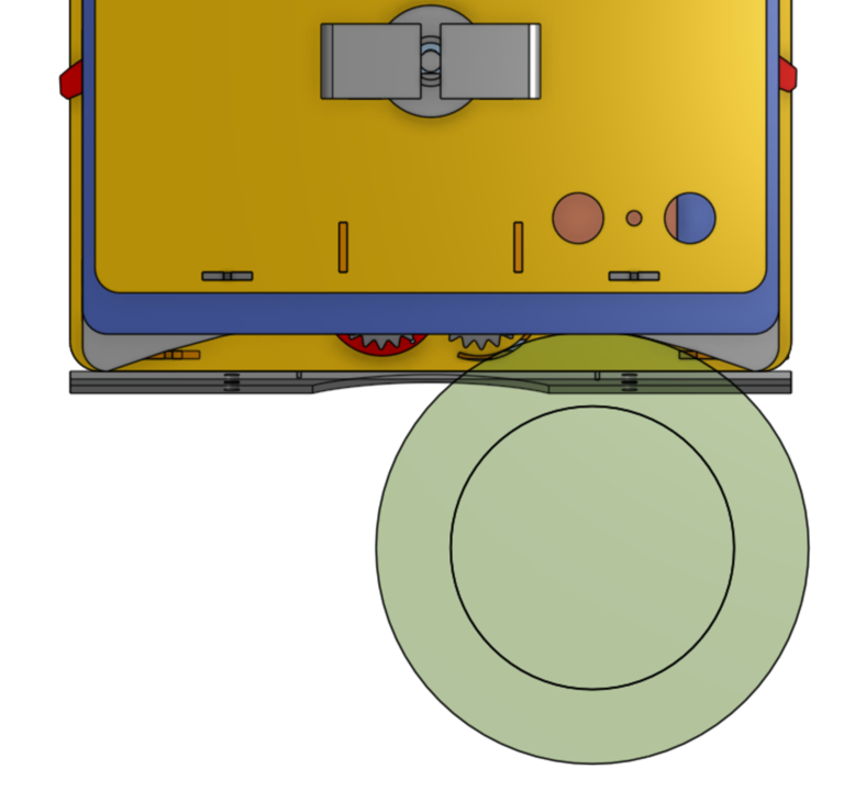
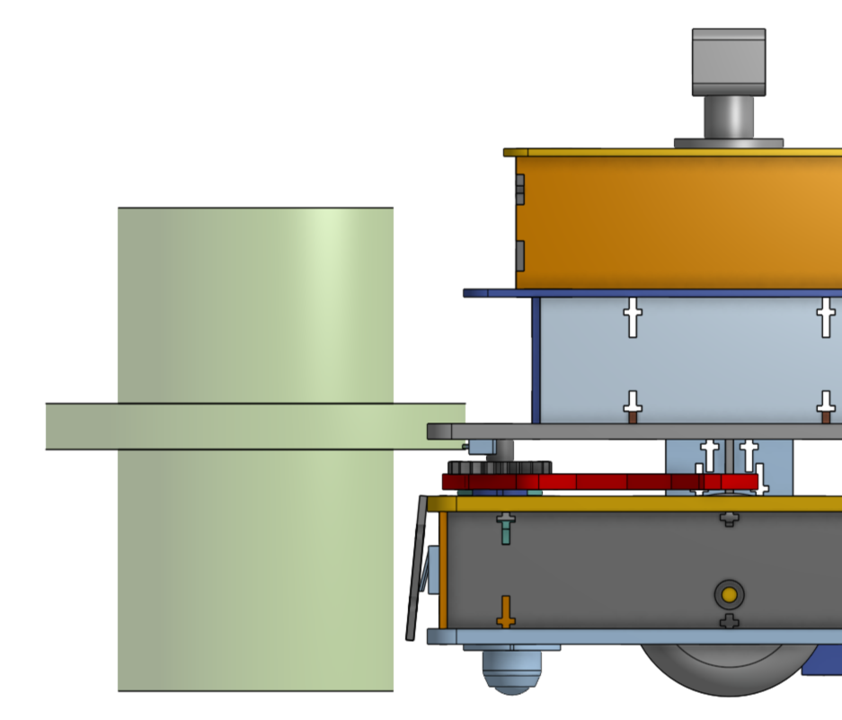
For collision detection, it is important to design the mechanism so as to avoid the miner from triggering bump while being captured by the grabbing mechanism but once it is captured and the bot is moving then any collision either to the bumper directly or to the miner should be detected.
This is accomplished using a curved plate which is engaged with the flange of the miner, and a cutout on the bumper which allows the miner to be placed at the center of the bot without triggering the switch.
This is accomplished using a curved plate which is engaged with the flange of the miner, and a cutout on the bumper which allows the miner to be placed at the center of the bot without triggering the switch.
|
|
At initial engagement, the flange of the miner contacted the curved plate such that there was a gap between the bumper and the miner (as shown in the figure above). This prevented the switch from getting triggered while the miner was being captured by the grabber.
The team discussed achieving this through software by disabling bump detection while grabbing the miner but decided not to use this approach because it was possible that the bot could bump into another object while grabbing the miner and would have failed to respond in this case.
The team discussed achieving this through software by disabling bump detection while grabbing the miner but decided not to use this approach because it was possible that the bot could bump into another object while grabbing the miner and would have failed to respond in this case.

|
|
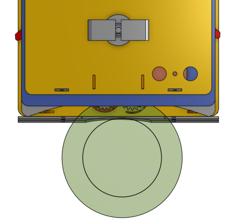
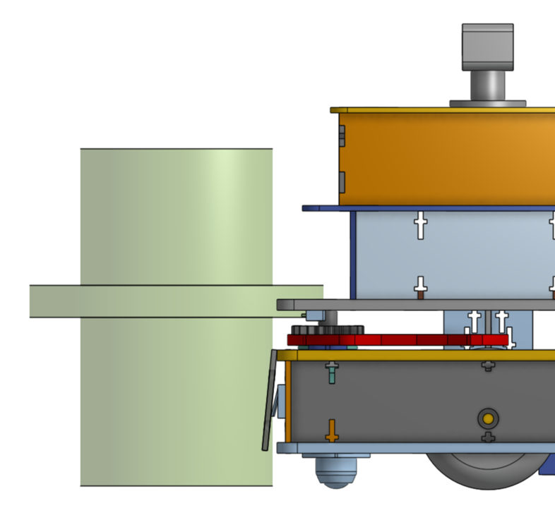
When the miner is positioned at the center of the bot, the bumper cutout prevents it from triggering the switch (as shown in the images above).

When the bot is moving with the miner, any collision with the miner would push the bumper at the top of the cutout and trigger the switch. A direct collision with the bumper would also cause the switch to be triggered. Therefore, in both cases, the bumper is able to successfully detect collision and respond to it.
Electrical Housing
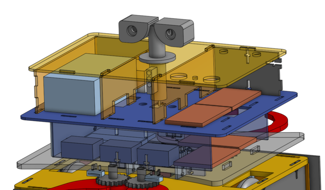
The two top tiers contain most of the electrical components as shown in the figure above. This allows ease of access to the components for debugging and gives ample space to house the components and route the wiring.
Manufacturing and Assembly
The gears, bushings, pillow bearings and sensor housings/mounts are manufactured using 3D printers to give more control over the design and dimensions of the bot while the rest of the parts are made out of duron using laser cutter to save manufacturing time and allow ease of assembly.
To assemble two separate pieces of duron together, + shaped slot design is implemented which allow them to be connected very easily by using a screw and a nut as shown in the image below.
To assemble two separate pieces of duron together, + shaped slot design is implemented which allow them to be connected very easily by using a screw and a nut as shown in the image below.

