
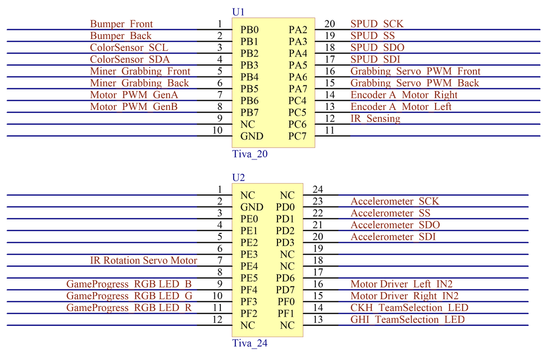
TIVA Board
IR Sensing Circuit
The IR sensing circuit is made of three stages. First stage is a linear signal conditioning circuit, second stage is a non-inverting amplifier, both the first stage and the second stage are built with MCP6294 quadruple op-amp chip. The third stage is LM339 comparator. On the first stage, we choose a small value of the feedback resistor to prevent OpAmp saturation during miner detection. On the second stage a gain of 30 occurs after an AC coupling filter with a corner frequency at 700Hz, which is much larger than the 60Hz frequency of ambient light noise. On the second stage we have a low pass filter with a corner frequency that blocks high frequency noises from being amplified with the desired signal. The output from the second stage is squared up using a compactor with the right values of hysteresis to only pick specific miner signal. Lastly the clean square waveform from the comparator is fed to port PC6 of TIVA which uses input capture interrupt to calculate the period of the signal seen by the IR sensor.

Bumpers Circuit
We had two bumpers, one in the front and one on the back. Each bumper is made of two parallel limit switches in normally open configuration. To prevent the switches pins from floating, we have used TIVA internal pull up resistors to pull them to 5V. Whenever one of the switches is triggered, its state changes from high to low and it indicates that there is a collision. We have implemented a software detour to avoid the collision path when we detect one.

Miner Grabbing Circuit
Two limit switches are used to command servos that control arc shaped arms that grab and hold the miners while we move them around. The switches are wired in parallel, configured in normally open mode and pulled to 5V by TIVA internal up resistors. When either of the two switches is pressed the servo change position from open to close. We have two identical circuit of this type, one in front to grab our miners and one the back to grab opponent miners during the competition.


Color Sensor Circuit
We used TCS34725 RGB color sensor to read different color gradient of the field during navigation. The color sensor and TIVA communicate over I2C.

Game Progress Circuit
Game progress circuit is made of a strip of RGB LEDs which lights up different colors depending on which portion of the game we are playing. Each color on the strip is switched on and off by an N-Channel Power MOSFET (IRLZ34N) configure in high side drive and the control signals come from TIVA. The control signals are passed through a Schmidt trigger (SN74HC14) to ensure a smooth transition from to high to low or vice versa.

Team selection LED circuit
Team selection circuit is made of two jumbo LEDs, two N-Channel MOSFETs (2N7000) and a single pole double throw switch. The red or blue LED indicates which company the bot is mining for, either the CKH company or GHI company and the single pole double throw switch is used to toggle between the two LEDs. We added two MOSFETs wired in low side drive and signal from these MOSFETs were used by TIVA to decide which company we belong to.

Accelerometer Circuit
We used the ADXL343 accelerometer to navigate the field. The accelerometer and TIVA communicates over SPI configured at 1.5KHz clock. TIVA is configure in master mode and accelerometer is configure in slave mode.

Encoder Circuit
The encoder circuit is made of a magnetic encoder kit which has a magnetic disc and hall effect sensor. The magnetic disc is mounted on the shaft of the motor and the hall effect sensor is mounted in proximity with the disc, hence Its output voltage is directly proportional to the magnetic field strength through it. The square wave output from the hall effect sensor is connected directly to an interrupt configured pin on TIVA and we use an input capture to calculate speed, distance and velocity of the bot. The circuit are similar for left and right motors.

Drive Circuit
The drive circuits are made of 2 LTE5206 chips, each chip has two half H-bridge circuits/ single full H-bridge circuit. In order to have a smooth drive, both chips were wired in Drive-Brake mode in addition to the PI controls. Each motor's duty cycle and direction were controlled with one PWM output from TIVA and two digital output pins from TIVA. Since the LTE5206 is made with MOSFETs which have inherently internal diodes we don’t have to add external flyback diodes.

Eye LED Circuit
We powered the bot eyes with two Green Jumbo LEDS wired in parallel and each has a 100ohms current limiting resistor.

SPUD Circuit
The field and the bot communicate over SPI, the SPI communication is handled by the Synchronized Permitting and Usage designator (SPUD). The SPUD is configured in slave mode and requires four TIVA pins and a 3.3V power line in order to function correctly. TIVA is configured as the master with an SPI clock frequency of 1.5KHz.

Power Distribution Circuit
The power distribution circuit is made of two ~7.5V batteries and 3 buck converters. The batteries are wired in series to produce a total voltage of 15V, this prevent the power line to the motor drive to sag while we are driving around. The first buck converter supply 5V power lines, the second buck converter supply 3.3V power lines and the last buck converter supplies 12V line. We have included a 3A fuse and two on-off switches in between the batteries. The fuse is primarily to prevent the motor drive from pulling huge amounts of currents from the batteries and the two switches give a possibility to switch between 5V and 15V power lines.

